
Alchemy Lab CV Outputs: Rates and Limits
alchemy-lab · alchemy-sdk · hardware-design
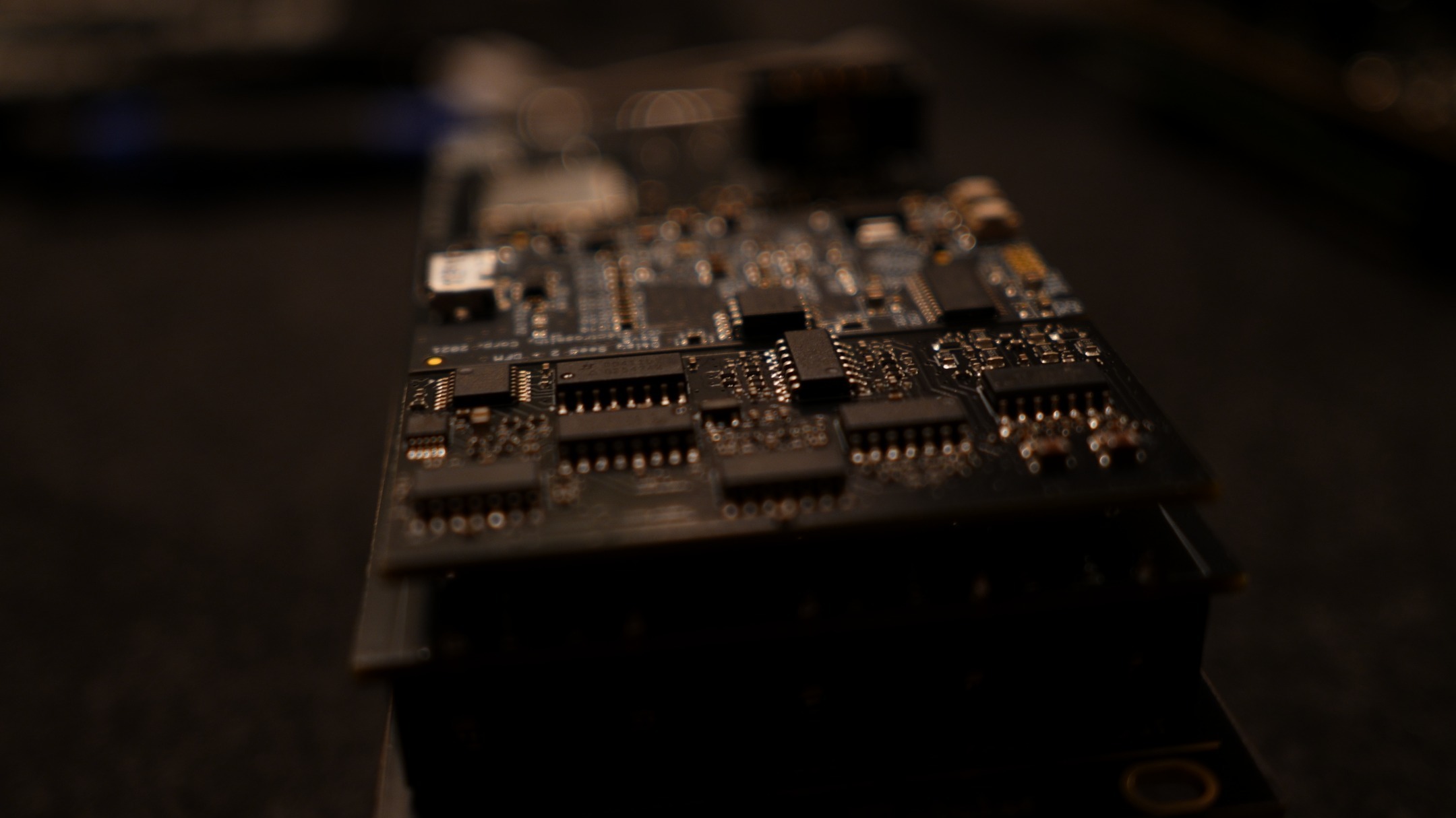
TLDR: hardware capabilities
The eight Alchemy Lab CV outputs use three different DACs: four share an external DAC, two use the processor's internal DAC, and two use the audio codec. They can all produce independent voltages, but their update rates and the software needed to drive them differ.
| Panel jacks | Hardware | What the hardware supports |
|---|---|---|
| J3–J6, also called CV 1–4 | MCP4728, four 12-bit DAC channels on a shared I2C bus | Thousands of updates per second. Updating fewer channels can be faster with a driver that sends only those channels. |
| J7/J8, also called CV 5/6 | Two independent 12-bit STM32 DAC channels | Audio-rate updates, such as 48 kHz, with timer-driven firmware. Their output data does not travel over I2C. |
| J9/J10, the audio outputs | Two DC-coupled, 24-bit codec channels | Audio-rate CV through the existing audio sample buffers, at the configured audio rate. |
Outputs have a nominal ±5 V range. J3–J8 can switch between input and output; J9/J10 are always outputs. As inputs, J3–J8 use a 16-bit ADC capable of audio-rate sampling, independently of which DAC backs their output mode.
What the SDK supports today
As of September 20, 2026, the Alchemy SDK's CvJack interface works with one voltage value at a time. The usual programming model is control-rate or block-rate CV, with no per-sample CV buffers for J3–J8 yet.
- J3–J6:
SetVolts()sends a blocking I2C transfer. For several outputs, useStageVolts()on each and then oneFlushCvOutputs(). - J7/J8:
SetVolts()writes the internal DAC directly. It is fast, but the SDK does not arrange a stream of evenly timed samples for you. - J9/J10: after
EnableCvOutput(),SetVolts()supplies one value for an entire audio block. For audio-rate CV now, leave the channel under your audio callback's control and write each sample yourself. - CV inputs:
ProcessAllControls()refreshes the values returned byVolts(). Those values are snapshots, not an audio sample history.
The default audio configuration is 48,000 samples per second in blocks of 24, so the callback runs 2,000 times per second. One new voltage per callback therefore means a 2 kHz update rate. A control loop running every millisecond instead gives about 1 kHz, before any work delays it. Neither number is a universal hardware limit.
Update rate is not waveform frequency
An update rate tells you how often a new voltage can reach the jack. A waveform's frequency tells you how often its full shape repeats. At 2,000 updates per second, a 10 Hz LFO gets 200 points per cycle; a 100 Hz waveform gets only 20.
You cannot interpret “2 kHz updates” as “a clean 2 kHz oscillator.” The theoretical frequency ceiling is below half the update rate, and useful waveform fidelity usually needs more samples than that, especially for shapes with sharp edges. Gates and triggers have a related limitation: a pulse shorter than the update interval can be missed or never appear at the output. Clock timing can only be as precise as the schedule that actually updates the jack.
J3–J6: how much speed does the shared DAC allow?
A DAC converts a number into an output voltage. The MCP4728 has four separate output channels, so these jacks can hold four different voltages continuously. They share the connection used to send new numbers: I2C, a serial bus configured at 400 kHz on the Alchemy Lab. More channel data takes more bus time.
For a custom driver using the MCP4728's selective Multi-Write command, the approximate bus budgets are:
| Channels updated in each transfer | Approximate updates per second, per channel |
|---|---|
| One | 10,000, or 10 kHz |
| Two | 6,000, or 6 kHz |
| Three | 4,000, or 4 kHz |
| Four | 3,000, or 3 kHz |
These are rounded estimates from the MCP4728 command format: one address byte plus three bytes per selected channel, including acknowledgement clocks, at 400 kHz. They assume immediate channel updates without extra latch transactions. They are bus-time estimates, not measured application rates or guaranteed maximums; other bus traffic and software overhead reduce them. Other command formats can change the budget.
Why the current API has different numbers
The current SDK implementation sends all four stored channel values on every MCP SetVolts() call, then pulses the DAC's latch through the I2C GPIO expander. That takes roughly 0.4–0.5 ms of bus time per call, leaving a ceiling around 2,000 calls per second before other work.
If you call SetVolts() separately for every active jack, that budget is shared: roughly 2 kHz for one, 1 kHz each for two, and 500 Hz each for four. These are optimistic bus budgets, not a recommended control-loop setting. Simply leaving three jacks unused does not make the current call send a shorter packet.
Batching avoids paying for the same four-channel transfer repeatedly:
// After hw.Init(), enable the jacks you want to drive.
hw.j3.EnableCvOutput();
hw.j4.EnableCvOutput();

// In your control loop, stage both targets and send once.
hw.j3.StageVolts(1.0f);
hw.j4.StageVolts(2.5f);
hw.FlushCvOutputs();
You can stage all four jacks this way for approximately the same transfer cost. Check the boolean return values in application code to catch failed writes. Keep these blocking transfers out of the audio callback: one transfer can consume nearly an entire default audio block's processing window.
For pitch sequences, LFOs, envelopes, and ordinary gates, these outputs are useful without a faster driver. If you need smooth modulation deep into the audio range, allocate one of the faster jacks.
J7/J8: two independent, faster CV outputs
J7 and J8 each have their own channel of the STM32's internal DAC. J7 can carry an envelope while J8 carries a different waveform. Using both does not divide the MCP bus budget, and traffic to J3–J6 does not consume their DAC transfer bandwidth.
These outputs still use the I2C-controlled switches when you change jack direction. Once connected, voltage updates go directly to the processor's DAC. ST specifies two 12-bit DACs with megasample-class capability, which provides headroom for rates such as 48 kHz. That converter specification is not a measured bandwidth guarantee for the complete jack circuit.
Today, calling SetVolts() once per audio block still produces just one new voltage per block. Calling it 24 times in a tight loop sends a burst of writes; it does not distribute them evenly across the next 24 audio samples. A hardware timer and sample buffer are needed for that timing, as described below.
J9/J10: audio-rate CV is already possible
The codec outputs are DC-coupled, meaning they can hold a steady voltage as well as reproduce changing audio. Each channel can carry its own signal. You can use one for audio and the other for CV, or both for CV, at the cost of those audio outputs.
With hw.j9.EnableCvOutput(), the SDK takes ownership of that channel and fills its buffer with the latest SetVolts() target after your callback returns. This is convenient for a steady voltage or block-rate modulation. Any samples your callback wrote to that claimed channel are overwritten.
For a waveform that changes at every sample, keep the channel in its default audio mode, or release it with DisableCvOutput(). Fill out[0][i] for J9 and out[1][i] for J10 in the audio callback. The SDK's nominal scaling is sample = volts / 5.0f, so a +2.5 V target corresponds to 0.5f. Keep values within the normal −1 to +1 audio range.
The codec clocks those samples out evenly. At 48 kHz, both channels receive 48,000 samples per second, regardless of the number of samples delivered in each callback. The codec's filtering and buffering still affect bandwidth and latency; CV through this path follows the same output chain as audio.
Resolution and voltage accuracy
J3–J8 have 12-bit output resolution: 4,096 possible codes over roughly 10 V, or about 2.4 mV per step. At 1 V/octave that is about three cents per step. This can be useful for pitch CV, but very fine pitch changes eventually encounter that quantization.
The codec's 24-bit sample format offers much finer digital steps. It does not promise 24 bits of real-world voltage accuracy. Noise, gain error, offset, and the analog circuitry affect the voltage that arrives at another module.
The SDK applies per-jack calibration to J3–J8; J9/J10 use nominal codec scaling and have no ADC readback through CvJack. For precision pitch work, verify the resulting voltage and tracking. The calibration article explains what the board measures and corrects. Calibration cannot add DAC bits or increase an update rate, and the output stages can become less linear near the ends of their range.
Addendum: 16-bit CV inputs and audio-rate support
All six switchable jacks, J3–J8, feed the STM32's 16-bit ADC, which converts voltage into numbers. Their input sampling capability does not depend on the MCP DAC's speed. The processor has enough conversion throughput for audio-rate CV acquisition with a suitable configuration, though channel count, sampling time, and oversampling all consume that budget.
The current SDK scans the pots and CV inputs continuously and uses DMA, a hardware mechanism that transfers samples into memory without the CPU copying each one. It keeps the latest reading for each channel. ProcessAllControls() then updates the public control values. Repeatedly calling Volts() inside your audio sample loop only rereads that processed value; it does not give you a sequence of fresh, synchronized samples.
J1/J2 have a different role: they are AC-coupled audio inputs. They can receive audio and detect trigger edges, but they cannot measure a held DC voltage. J9/J10 have no input mode. The jack-switching article covers how the six configurable jacks connect their input and output circuits.
What needs to change in the API?
Reliable audio-rate CV input and output needs additional memory regions holding sequences of samples, alongside the existing audio buffers. A hardware timer would schedule the ADC measurements and the J7/J8 DAC updates at regular intervals, with DMA moving values between those peripherals and their buffers.
The application could then receive a block of CV input samples and fill a block of CV output samples. While it processes one buffer, the hardware works through another. The API needs to define which channels participate, their sample rate, how CV timing lines up with audio, and when each buffer is safe to read or write. Calibration must also apply consistently to those samples.
That integrated design has not been implemented yet. It requires changes to ADC scanning, buffer allocation, timing, and the callback interface, followed by testing alongside audio and the rest of the controls. This is why it will take some development time. The MCP outputs would retain their shared bus limitation even after that work.
You can implement the lower-level timer and DMA support in your own firmware today, or open an Alchemy SDK issue requesting it. Include the jacks you need, the desired sample rate, and what you are building, or add that information to an existing request. To start with the current API, follow the Alchemy SDK setup guide and the CV playground example.